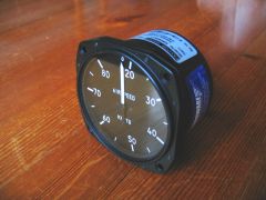
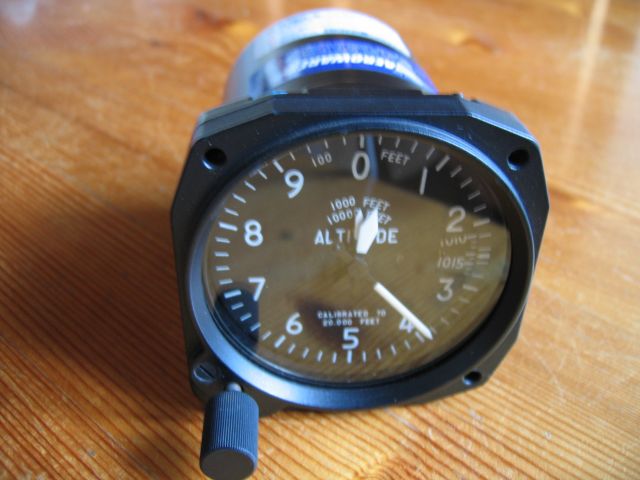
Collected an airspeed indicator, and ordered a compass, altimeter and strobe from Aeroware.
Ordered the engine mount - basically some strategically bent aluminium and rubber vibration isolators.
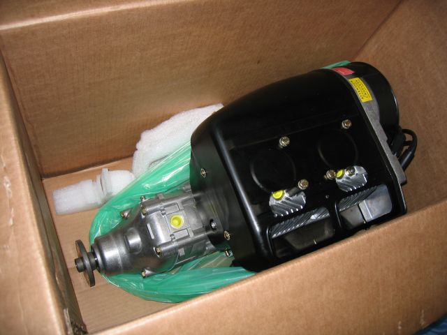
One brand-new Rotax 503, and its instrumentation.
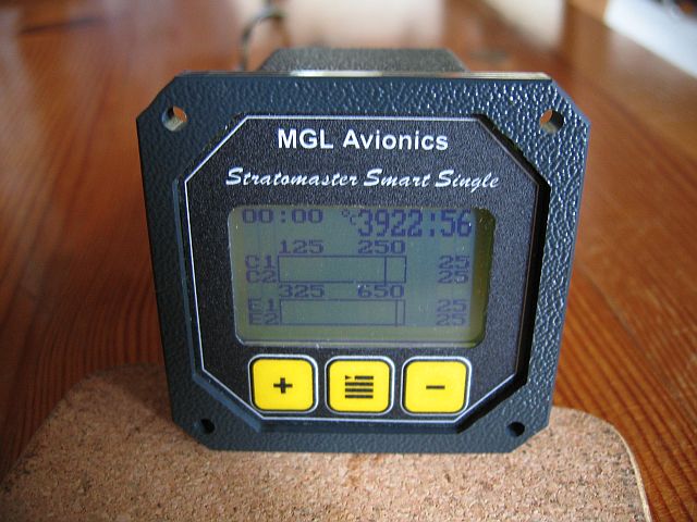
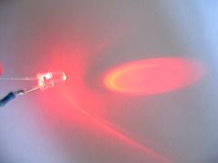
A road trip today - first to Hamilton, where I bought an EMS-503 LCD engine monitor from Stuart Parker, and then on to Tauranga to collect the engine itself from Colin Alexander of Solo Wings. On the way back along State Highway 2, in the middle of nowhere, was a huge sign saying "LEDs". I went in and purchased an flashing red ultra-bright specimen. It will be connected to the external alarm contacts of the EMS.
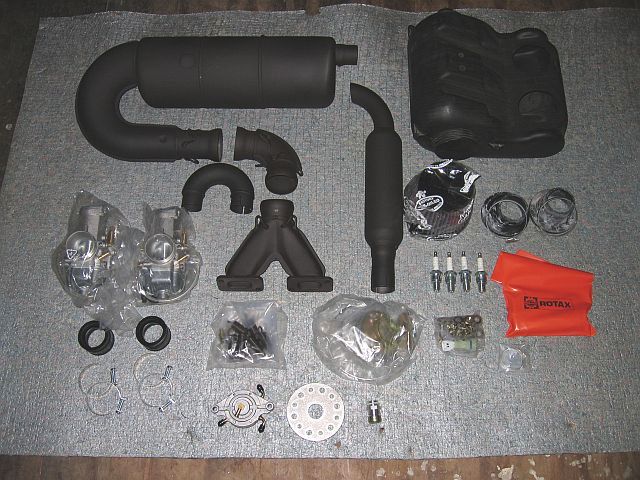
Got around to sorting through the various packages that came with the engine.
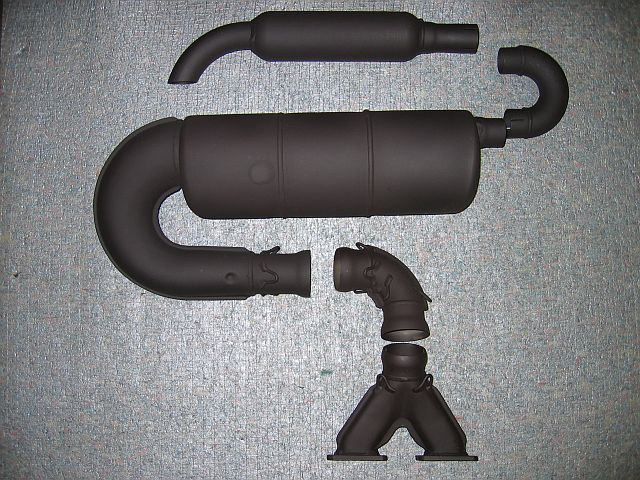
At some stage the exhaust system will get a ceramic coating applied to it, so I've taken a "before" shot.
Chatted this morning with Lonnie Prince, of Prince Aircraft, and will almost certainly be using one of his propellers.
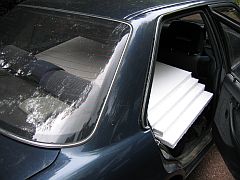
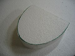
I'm going to have to build my own fibreglass instrument pod - none of the commercially available models will hold all the instrumentation I want. So I've acquired some MDF, and perhaps a little more polystyrene than strictly necessary to build the mould.
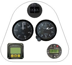 With the help of MS Paint, and the free Proge CAD LT,
I've finalised a panel
layout I'm happy with, and which satisfies the following criteria:
With the help of MS Paint, and the free Proge CAD LT,
I've finalised a panel
layout I'm happy with, and which satisfies the following criteria:
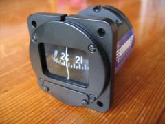
The compass was the major fly in the ointment - it's mandatory equipment, and many pilots satisfy that requirement with cheap and nasty stick-on units from the $2 Shop. (Some, as a protest, mount them halfway down the tail - the rule doesn't say WHERE the compass has to be located.) I couldn't bring myself to do that. And if you're going to have a compass in the panel, then it might as well be treated as a serious flight instrument and mounted accordingly.
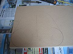
 Refined the panel some more; added a 10mm strip around the edge, to allow for the lip in the pod on which the panel will
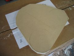
actually sit and get screwed to. Armed with a satisfactory design, I marked up the MDF base of the mould, rough-cut it,
and then started sanding it down to its final shape.
Refined the panel some more; added a 10mm strip around the edge, to allow for the lip in the pod on which the panel will
actually sit and get screwed to. Armed with a satisfactory design, I marked up the MDF base of the mould, rough-cut it,
and then started sanding it down to its final shape.
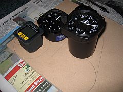
Marked up, and then sanity-checked against the real equipment.
Ordered a carbon-fibre P-tip propeller from Prince Aircraft. Many thanks are due to Brian Jackson, a fellow Bee-builder, for putting me on to these :)
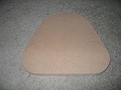 Finished sanding the base of the mould, and did some more CAD work, this time in 3D, to establish the contours of the shell itself.
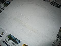
Yet more CAD work on the backshell contours, and the process of transferring them to polystyrene. The plots wouldn't fit on a single sheet of A4, so some strategic cutting and taping had to be done.
This morning I collected the fibreglass mat, West System resin and some fairing compound from Adhesive Technologies.
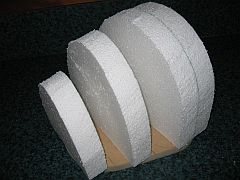
Tonight was spent cutting out polystyrene slabs using a hacksaw (a strangely satisfying activity) and gluing the slabs onto the MDF base.
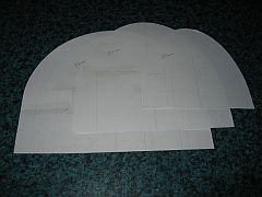
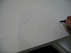
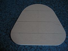
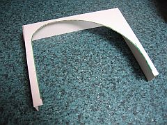
 Today started with cutting the last couple of contour-slabs, and gluing them to the base. I then printed the single
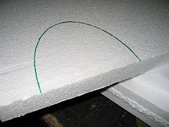
longitudinal contour and used it to construct a cardboard test jig.
Today started with cutting the last couple of contour-slabs, and gluing them to the base. I then printed the single
longitudinal contour and used it to construct a cardboard test jig.
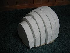
 When the glue had set, I started rough-cutting with the hacksaw.
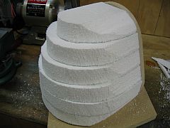
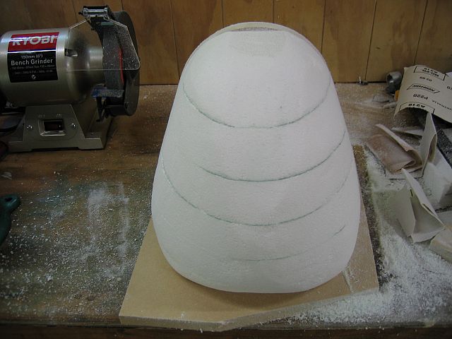
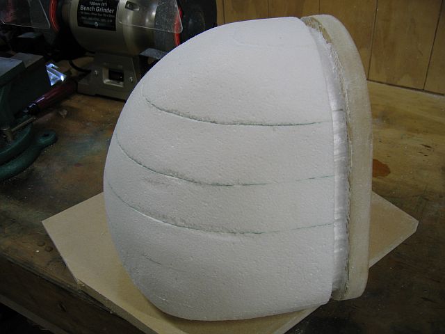
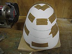
Cutting was followed by sanding using 100 grade sandpaper, and periodic testing with the jig.
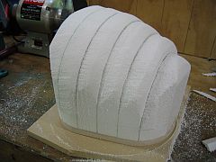
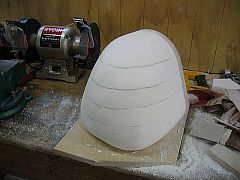
After sanding - almost done, but need to do something about the 5mm segment at the top.
That chunk will get cut and sanded down to shape. Next step will be fairing compound to fill in the gaps & voids.
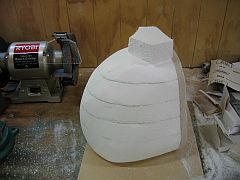
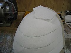
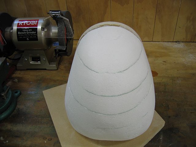
Rough-cut and sanded the new top section of the polystyrene mould.
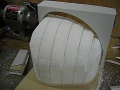
The next bit was something of a challenge. The shell has a 10mm deep lip around the edge, to which the instrument panel will be fastened. This necessitates digging a trench in the mould:
 I'm also contemplating creating a sort of strengthening web using the same process.
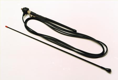
Did some research around radio antennae, since I need to know what (if anything) is going to be attached to the pod. As there's no ground plane available, I'm going to use an Airkit G1 ground-plane-independent dipole, mounted on a bracket external to the pod. This goes with the decided-upon-but-not-yet-budgeted-for XCOM 760 transceiver.

 Saved from having to worry about antenna mounting issues, I did some more CAD work and defined the hard mounting points.
In addition, two strengthening members will be moulded in, running longitudinally down the centre of the pod, and
horizontally around the widest circumference, intersecting the hard points.
Saved from having to worry about antenna mounting issues, I did some more CAD work and defined the hard mounting points.
In addition, two strengthening members will be moulded in, running longitudinally down the centre of the pod, and
horizontally around the widest circumference, intersecting the hard points.
Ordered the antenna.
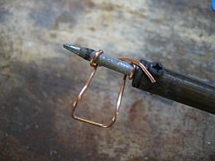
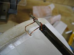
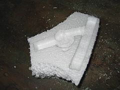 This evening I decided to test the strength of fairing compound as a structural element,
and it evaluate it as a means of creating the hard points.
I filled a polystyrene mock-up with the stuff, and used the remainder to fill the worst of the voids on the mould itself.
This evening I decided to test the strength of fairing compound as a structural element,
and it evaluate it as a means of creating the hard points.
I filled a polystyrene mock-up with the stuff, and used the remainder to fill the worst of the voids on the mould itself.
An inconclusive and vaguely frustrating evening. The fairing compound isn't quite as strong as I'd hoped, but then again I think I added way too much filler. The problem is how to keep it in place if it's too thin. I *did* have the fun of melting the polystyrene off the test piece using acetone... the stuff just magically disolves into nothing.
Experimented with draping the glass cloth over the actual mould - and it looks like the thing is going to be composed of inch-wide strips.
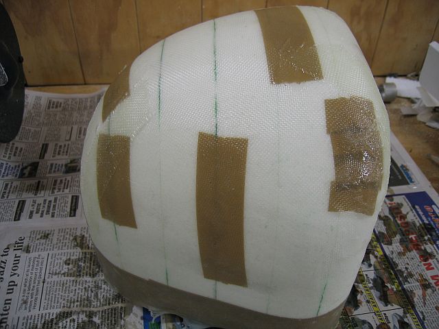
 I gave up the concept of moulding in the hard points and the lip for the panel while doing the shell layup. The only way to
get the fairing compound strong enough is to mix it up too runny to mould. So this evening I set about laying up the first
layer of the shell. First step was to tape up the trench dug for the lip, and the various patches of fairing compound.
The exposed polystyrene will bond to the shell - but will be dissolved away using acetone.
I gave up the concept of moulding in the hard points and the lip for the panel while doing the shell layup. The only way to
get the fairing compound strong enough is to mix it up too runny to mould. So this evening I set about laying up the first
layer of the shell. First step was to tape up the trench dug for the lip, and the various patches of fairing compound.
The exposed polystyrene will bond to the shell - but will be dissolved away using acetone.
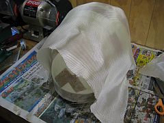
 Then came the exercise of draping the glass cloth over
the mould. I finished up using one single square piece of cloth and using strategic cuts to help it fit the contour of the
mould.
Somewhere during this process I got thoroughly fed up trying to get bloody-minded segments of cloth to cling to impossible
curves, and decided to put my trust in a higher power: West System epoxy.
Then came the exercise of draping the glass cloth over
the mould. I finished up using one single square piece of cloth and using strategic cuts to help it fit the contour of the
mould.
Somewhere during this process I got thoroughly fed up trying to get bloody-minded segments of cloth to cling to impossible
curves, and decided to put my trust in a higher power: West System epoxy.
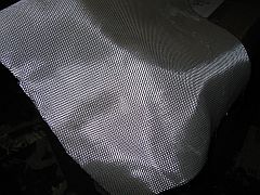
I mixed up a 72mL batch of resin (one full 60mL syringe of resin) and set to work wetting out the cloth. What an amazing processs - the cloth turns completely transparent and its dynamics change completely. Suddenly it became incredibly easy to smooth the stuff around corners and have it stay there.
 About two-thirds of the way through, I ran out of resin and had to mix up another batch. I finished wetting out the existing cloth
and then setting about patching the gaps with bits of cloth cut on-the-fly. Again, a remarkably easy process.
About two-thirds of the way through, I ran out of resin and had to mix up another batch. I finished wetting out the existing cloth
and then setting about patching the gaps with bits of cloth cut on-the-fly. Again, a remarkably easy process.
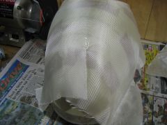
There are some rough patches, but I'm confident these will come out in the wash with some sanding prior to the next layer.
 Sanded down the first layer, removing rough patches and feathering the overlapping joins. Draped and cut the three pieces
of cloth that will become layer #2.
Sanded down the first layer, removing rough patches and feathering the overlapping joins. Draped and cut the three pieces
of cloth that will become layer #2.
 Unfortunately I can't proceed with the actual layup till I acquire some more measuring cups. Mańana.
Went shopping this morning and acquired some disposable acrylic measuring cups. Came home and applied the second layer of glass. This one's definitely going to need sanding - I was plagued by rogue strands of glass coming loose from the edges of the mat, getting entrained in the brush and then depositing themselves in unwanted places. But at least this time there was much less mess - disposable gloves an advantage.
And have just received word that the vast array of bits including the mast, keel and tail tubes is about to depart StarBee.
Sanded down layer 2 in preparation for layer 3.