Contact from StarBee, with photos of their version of the pedal mounting bracket. After due consideration I'm going with a solution proposed by Brian Jackson, which uses the existing 0.125" bracket reinforced back-to-back with another smaller brace which is bolted to the existing holes in the nose block.


Also sprayed another dose of undercoat at the drag struts.
Got the airframe back from being polished and anodised. The results are stunning, and with a coat of fluorescent scarlet on the drag struts tonight, the final colour scheme is now evident.


Put the final gloss coat on the drag struts, and parked them safely out of the way without any further disasters.
Started on the seat mount today - cutting the four plates. Made somewhat easier by carefully using two square edges on each sheet, thus reducing the cutting & filing by half.

Put another "final" coat on the drag struts.
Match-drilled the seat plates, and then deburred them. 104 separate operations. Urrgh.


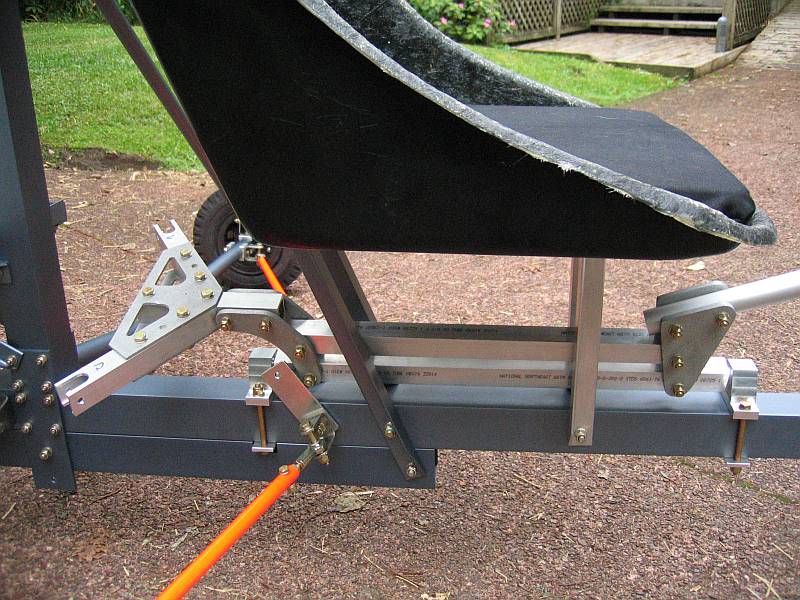
Strategic use of clamps enabled me to remove each seat brace from the airframe in turn and use the rear plate as a jig for the drilling.


Not a lot got done today - our mailbox was vandalised overnight and several hours were spent on repairs once the upper half had been retrieved from up the road.
Did manage to drill the rear of the seat to take the plates. The main challenge here was how to locate the precise centre of a surface with very curvy edges, and I finally resorted to extending each side of the base rearwards with some scrap angle to provide a reference edge.


Nothing achieved this evening bar the reassembly of the drag struts. As with many other components, the bolts could afford to be shorter.

Drilled the bottom of the seat to take the plates. Further progress came to an abrupt halt when I discovered less usable angle on hand than I thought.

Cut the angle required for the lower seat rails and the vertical struts. Drilled the rails - having first discovered a discrepancy in the plans - the rails have to be inset 1/8" from the plate edges to line up with the keel.

Clamped the vertical seat struts into position, and marked the struts and the keel for drilling. Removed the keel from the airframe and pilot drilled through both walls in one pass, prior to drilling the full-size 1/4" holes separately.
Finally reassembled the aircraft in preparation for a visit from Duncan Meyer, a fellow rotorhead.
Had to rebuild one lower seat rail this evening, and both vertical struts, as there wasn't enough overlap at the bolt. Probably a dose of paranoia, but it's a peace-of-mind thing.
Final approach to the vertical struts... match drill the lower 1/4" hole in both struts, 1/2" from the end. Test-fit them to the airframe and file down the top end of each strut to nest comfortably in the seat rails. Clamp the parts together, using an additional piece of scrap angle, remove from the seat, and drill. Observant 'Bee builders may notice that the vertical struts differ from the plans... the flat side-wall of the angle faces aft, not forward, to provide a surface to which I can mount other equipment under the seat, not least the switch panel. The struts are also set 1/2" aft relative to the plans, which makes it significantly easier to get a socket on the various nuts involved.
Spent the last couple of days either incubating or suffering from the 'flu.
Worked up enough energy to make the fairing cuts in the seat mounts, and to bolt the control stick and linkages into place, before being carried off to Wellington for the weekend.
Started the discovery process around mounting the engine. More questions raised than answered... the engine has four threaded studs screwed into the crankcase, presumably for mounting purposes. There doesn't seem to be any other fixing hardware, or even any information in the manual around what diameter & thread (presumably metric) has been used. Does one use the studs? Replace them with bolts? What?
Following advice from the vendor, I managed to find the mounting nuts and washer in an obscure plastic bag in the engine kit. Still a heap of unanswered questions - the engine studs are so long they're going to protrude through both halves of the engine mount and conflict with the only feasible location of the airframe bolts.
Not a particularly successful evening last night. The engine mount is on hold, pending the acquisition of bolts and washers, so I attacked the cheek plates. First order of business is to set up a jig patterned after the holes in the top of the mast. While fiddling around up the mast I dropped a bolt which took a chunk out of the paint on the drag struts. Touched up this morning, but am not happy.
This evening, after much fiddling with clamps, bolts & drills, I successfully transferred the bolt pattern at the top of the mast to a jig (recycled cluster plate) which will be used to drill the rotorhead cheek plates. Next step - the rotorhead pattern.
This morning I rebuilt the jig for the mast-head pattern after discovering binding problems when inserting bolts. This evening, another scrap cluster plate was recycled to build a jig for the rotorhead bolt pattern.
Armed with these two strategic pieces of metal, it should now be very easy to build the rotorhead cheek plates.

Constructed the first of four 2" x 2" x 3/16" spacers. These are intended to increase the distance between the pairs of aluminium bar that make up the engine mounts, and thus provide enough room for both the crankcase studs and the airframe bolt heads to coexist peacefully. Four more 1/2" thick spacers will live between the engine itself and the mount, absorbing the rest of the stud length.
Not a lot done tonight - a persistent cold has me in thrall. Rough-cut the remaining 3/16" spacers for the engine mounts, and filed & dressed one of them. Two to go.
Filed the remaining spacers, and drilled all four. I am NOT looking forward to doing battle with the lengths of 1/2" bar needed for the thick spacers. Next step is to fabricate a couple of small 1/8" plates to reinforce the underside of the engine bearers where the bolts anchor the mount to the airframe.
Nipped out at lunchtime and bought a chain hoist for manoeuvering the engine.
Unfortunately nothing else got done, the evening was spent up a ladder retrieving two of our cats from two separate trees after an incursion by the neighbours' evil hound.