
Installing the engine is the most complex part of the build and also the least documented, so I've created this page to chronicle the ongoing saga of turning a Rotax 503 and a Gyrobee airframe into a functioning aircraft.
Installing the engine is the most complex part of the build and also the least documented, so I've created this page to chronicle the ongoing saga of turning a Rotax 503 and a Gyrobee airframe into a functioning aircraft.
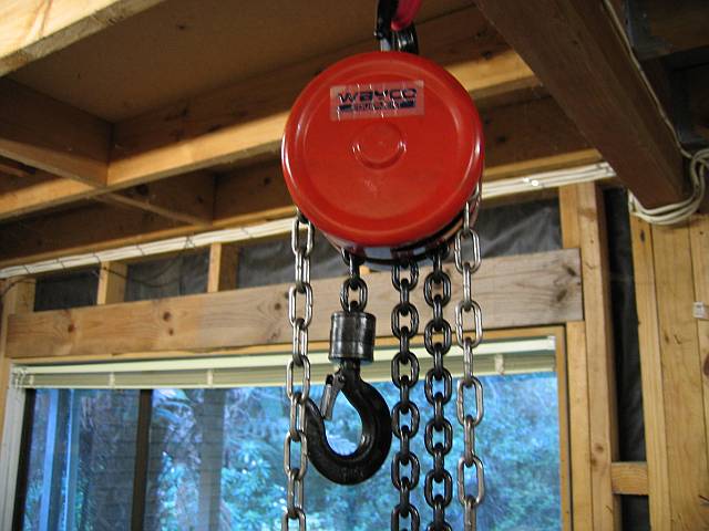
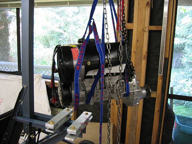
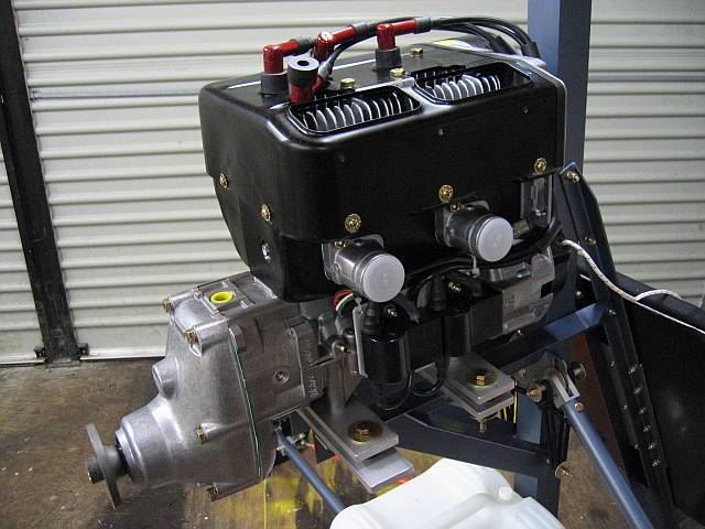
In the great scheme of things the 503 isn't a particularly heavy engine, but moving thirty-five kilos around by hand is inconvenient at best and in some cases downright dangerous (although maybe I'm just a wimp). In any case, a chain hoist has been acquired, which will no doubt see further duty when it comes time for the hang tests.

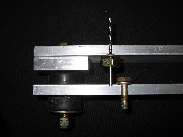
I'm using engine mounts supplied by StarBee, which like pretty much all other mounts, consists of two lengths of aluminium bar separated by rubber vibration isolators. These mounts bolt crosswise to the airframe engine bearers, and the engine in turn bolts to the mounts.
Problem: The four studs protuding from the underside of the engine are relatively long. So long in fact that they would pass right through BOTH halves of the mount. Further, the bolts which anchor the mounts to the airframe and the nuts on the engine studs all have to coexist inside the mounts, and there just isn't enough room.

![]()
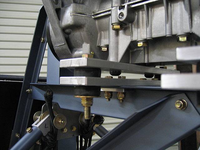
Solution I: Initially I followed some very sage advice and several flying examples, and fabricated spacers to increase the clearance within the mounts. This approach raises the engine and hence the thrustline relative to the aircraft's centre of gravity.

Solution II: After receiving some more (and different) advice, I adopted a different approach. I removed the studs from the engine and replaced them with button-headed bolts installed from underneath.
Actually removing the studs from the engine proved to be a challenge; resolved by using two of the nuts and a compression washer to get a lock on each stud.
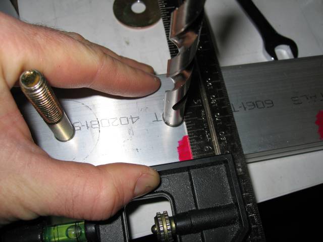
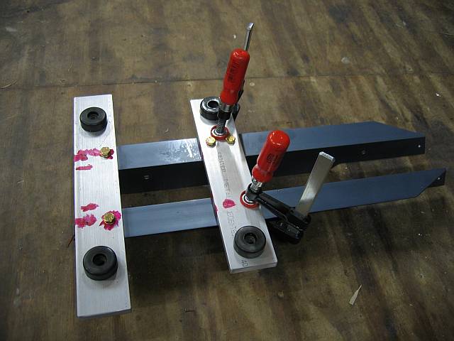
Actually positioning and bolting the mounts to the bearers was something of an involved process. The first challenge was to establish a reference datum on the mounts, using the existing holes, a drill bit and a square. Having established where the aft mount should live (laterally), it was drilled and bolted at one corner.
To establish the location of the forward mount and to get the installation square, I lowered the engine into place on the mounts. With some of the weight still carried by the hoist, I was able to nudge the engine into alignment, checking continually with a square applied to the forward mount. Everything was clamped and the engine removed, before disassembling one or both bearers from the airframe and drilling. This was something of an iterative process, and I was relieved to tighten the bolts on the bearers for the "final" time.
Copying a very sensible installation detail from Rick Martin's 'Bee, the airframe bearers themselves are reinforced at the bolt holes with small 3/16" plates...
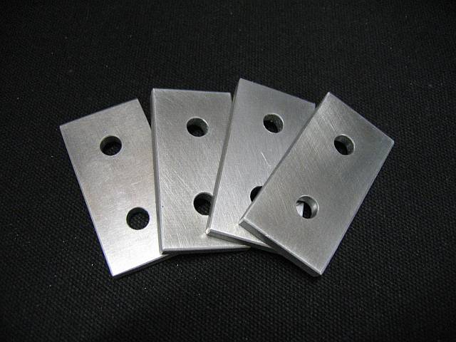
... the final step before actually mounting the engine:
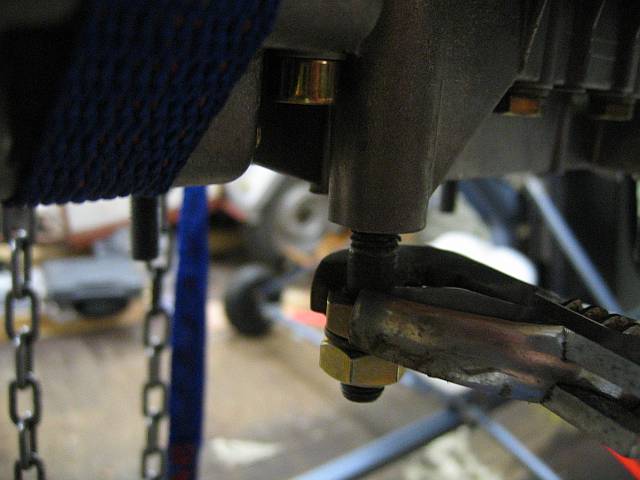
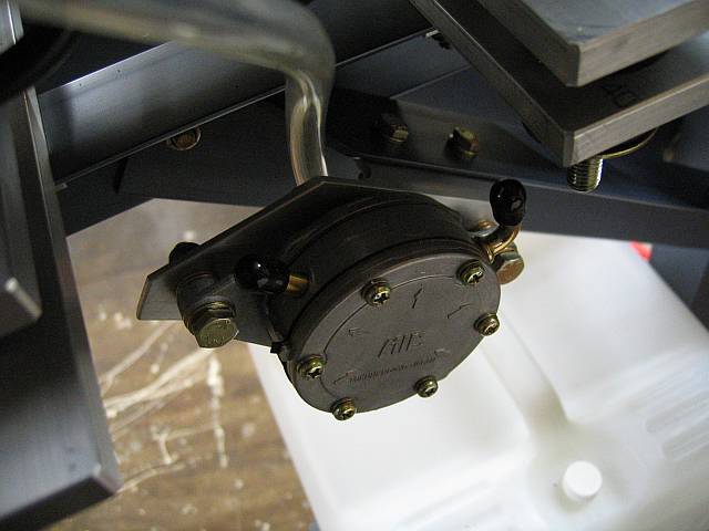
 The Rotax 447 used by Ralph on the original Bee had provision for mounting the fuel pump on the engine.
The 503 DCDI does not provide such luxuries, and there are certain constraints which must be followed when
finding a suitable location for it. The impulse line from the crankcase must be no longer than half a metre,
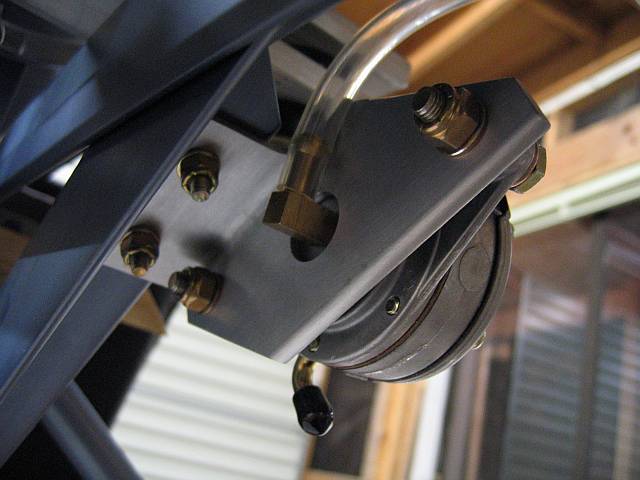
and the pump must be mounted somewhere at ambient temperature. The only logical location seems to be on some part of the
engine bearers, and so I've designed a bracket to mount high up on the right-hand diagonal strut.
The Rotax 447 used by Ralph on the original Bee had provision for mounting the fuel pump on the engine.
The 503 DCDI does not provide such luxuries, and there are certain constraints which must be followed when
finding a suitable location for it. The impulse line from the crankcase must be no longer than half a metre,
and the pump must be mounted somewhere at ambient temperature. The only logical location seems to be on some part of the
engine bearers, and so I've designed a bracket to mount high up on the right-hand diagonal strut.
I ordered the side-mount exhaust kit, and after some preliminary investigations and head scratchings, have decided to mount it canister-upwards, using brackets attached to the cylinder-head studs. There are a couple of issues - the cooling shroud is supported on spacers attached to four of the eight studs, but not in a useable configuration. An extra hole needs to be drilled in the shroud, and a spacer swapped for the nut on the adjacent stud.
Also to be rectified, the way I plan to mount the exhaust, the little welded loops on the elbow fitting are precisely 60 degrees out of alignment with their counterparts on the muffler, a situation which Rotax specifically caution against. To avoid over-stretching the springs, the loops will need to be removed, and new ones welded on in the correct position. This is no doubt why a bag of spare loops was supplied with the engine.
In the end I ordered the Exhaust Mounting and Ball Joint Conversion kits from California Power Systems.

 The CPS exhaust kit consists of clamps, rubber isolators and brackets.
These brackets bolt to the spacers holding the cooling shroud on, which in turn are mounted on the cylinder head studs.
The CPS exhaust kit consists of clamps, rubber isolators and brackets.
These brackets bolt to the spacers holding the cooling shroud on, which in turn are mounted on the cylinder head studs.
There's an issue - although there are eight studs, the four chosen by Rotax to anchor the shroud aren't in a useable pattern.


CPS supply a paper template with which you're supposed to be able to drill the additional holes.
 Unfortunately the spacing shown on the template bore only a faint resemblance to physical reality; somwhere along the way the
document seems to have been scaled down about 5%, rendering it useless.
Unfortunately the spacing shown on the template bore only a faint resemblance to physical reality; somwhere along the way the
document seems to have been scaled down about 5%, rendering it useless.
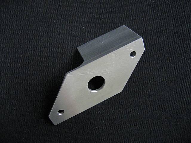
Finally I was forced to construct my own drilling jig out of 1/16" aluminium, after which drilling the three extra holes and swapping over the spacers proceeded relatively smoothly.


 The ball joint conversion kits which eliminate the springs are straightforward to install. The instructions recommend removing the loops completely, but they're not in the
way, so for the time being they can stay.
The ball joint conversion kits which eliminate the springs are straightforward to install. The instructions recommend removing the loops completely, but they're not in the
way, so for the time being they can stay.
With the jig already constructed for the cooling shroud, drilling the brackets and completing the exhaust installation was painless. Still need to re-torque the nuts on the cylinder heads, apply locktite to the ball-joints, and safety wire the clamps, but this can all wait till the whole exhaust comes off again to get its ceramic coating.

This is proving to be something of a learning curve with some serious real-world consequences for inattention to detail... the carburettor slides are held naturally closed by springs, and open under tension applied to the throttle cable. There are two particularly interesting ramifications to this:
(a) Excessive friction in the cables and linkages will make it harder to open the
throttle, and can make it impossible to close. (If this happens when taxiing towards a parked aircraft, it's quite an
adrenaline rush)
(b) The throttle defaults to CLOSED - therefore any breakages, disconnects or swage failures in the system
will produce the next best thing to an engine failure, sorry, "uncommanded shutdown".
The engine comes with two Bing 54 carburettors; how you go about controlling them is up to you. The various online stores present a bewildering array of cables, swages, ferrules, fittings, quadrants ad nauseam, but no information on what you actually need to assemble a functioning linkage. Dual carburettors complicate the process because at some point the single cable from the throttle needs to split into two. The only thing in my favour is that I'm not using the choke.
A 'Bee builder in the US kindly provided me with a specific parts list, which I then ordered from CPS. It consists of:
 After getting very well acquainted with the intricacies of the Bing 54 (attaching the cable to the slide requires octopus-like
fingers and is performed while battling against a spring), I encountered problem #1: The 20 inch carburettor cable supplied was made up to the wrong length - the inner cable is too short to
even let the slide close completely... and a replacement is on it's way.
After getting very well acquainted with the intricacies of the Bing 54 (attaching the cable to the slide requires octopus-like
fingers and is performed while battling against a spring), I encountered problem #1: The 20 inch carburettor cable supplied was made up to the wrong length - the inner cable is too short to
even let the slide close completely... and a replacement is on it's way.
Yet another piece of engineering in which you're left to your own devices. Two big rubber adaptor flanges with slotted rims mount the silencer to the carburettors, but the silencer (and air filter) is still basically hanging in space.


Mounting tabs are provided in several places, and fortunately two of these are positioned close enough to the engine mounts to be usable. I fabricated a pair of brackets from 1/16" sheet, using cardboard cutouts to test the dimensions.


To be continued...